Speedo converter HELP!!!!!


JIMBOB-EK9

Moderator
Donator
Joined
Jun 24, 2007
Messages
2,665
My 9 is converted to MPH but still has the speed limiter in place!:angry:

I have just took the clocks out to run a wire to the ECU from the convertor, but he convertor is not just wired into the loom as usual!:((

The convertor has been soldered to the back of the clocks (onto the ribon cables)
here is a pic of how it is now!
8960a980.jpg


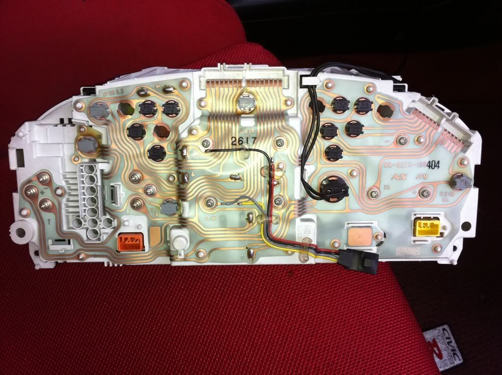
Im now thinking that choping into this & trying to run a wire to the ECU will not work & the best option would be to remove the convertor from the back of the clocks & refit it at the gearbox end as i have always fitted them befor????

anyone else have a opinion/better idea??
 
i used to work for a importer and you do find different ways of fitting chips to different cars on toyota the way yours is done is the way forward works fine but the honda ecu must get the signal before the clocks if your limiter is still working at 180km obviously the chip will not remove the limit only convert it to 180mph so moving it to gearbox end should fix the problem
 
forgot to add you will of course need to re connect the ribbon where no doubt it will be cut in between the grey and yellow wire
 
Cheers for your replys mate!

I just can't decided weather running a wire from the grey wire to the ECU will work or just just refit at gearbox end as said.......

I'm going to have a play with it anyway soon as the mrs gets back from the gym!:naughty:
 
Last edited:
I reckon splicing into the grey wire from the clocks will be the same thing as having it wired in at the gearbox end man. S'long as the ECU receives the chipped signal your all good aren't you?
 
Just take a feed from the grey wire screw and run this to the ecu speed sig wire. Cut the ecu speed sig wire and fix the new run wire to ecu then just blank off the other cut wire.
Dunx
 
I reckon splicing into the grey wire from the clocks will be the same thing as having it wired in at the gearbox end man. S'long as the ECU receives the chipped signal your all good aren't you?

Just take a feed from the grey wire screw and run this to the ecu speed sig wire. Cut the ecu speed sig wire and fix the new run wire to ecu then just blank off the other cut wire.
Dunx

I thought about doing it this way guys, but them thought that if i chop into the signal wire at the ECU then how would the yellow wire (speed convertor) be getting its feed????

Anyway its a little late now as i removed the convertor off the back of the clocks last night!:((

I went to refit it at gearbox end but the wire colours did not match up to all the instruction on hear!

All instructions on hear say the wires are-
yellow/white = signal wire
blue/yellow = 12v ing live
black = earth

What i have on my loom is-
blue/white = ???
yellow/black = ???
black = earth

i didnt have my multimeter with me to test the wires last night so i just left it till this morning when i have more light & the correct tools!:nice:

Can anyone confirm which colour wires are which befor i start testing them???
black
 
Back
Top