FIRSTLY, THIS IS AN EXTRACT FROM THE CIVICJORDAN.CO.UK FORUM BY
G-G (031/500) SO ALL THE CREDIT GOES TO HIM. I CANNOT TAKE ANY CREDIT OR QUESTIONS FOR THIS

Disclaimer: This is how i have done my conversion, it has worked for me but if you break your mirrors/car following these instructions dont blame me. You will need a basic ability and understanding of elctronics
First things first, get some mirrors, i got mine from ebay which is probably the cheapest resource, but they are also available from some JDM specialists such as
JDM Honda Parts, JDM Honda Engines / JDM Nissan Motor Swaps, Used JDM Parts | Password JDM amongst others.
They are however fairly rare and as such may not be in tip-top condition. This dosent really matter as you arent going to be using the new casings, you will use your yellow ones (unless these are broken in which case you will need new housings as well).
Ensure that they come with:
Left and right mirrors
Relay box
Mirror position and fold switch (not essential but might be useful)
All wiring harnesses for the above
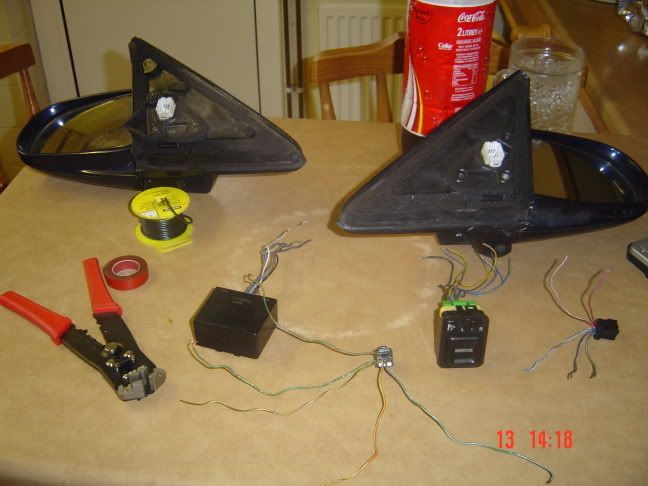
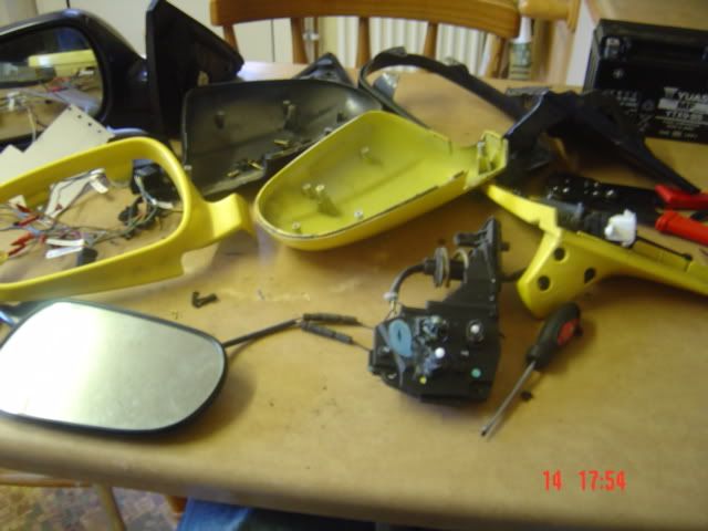
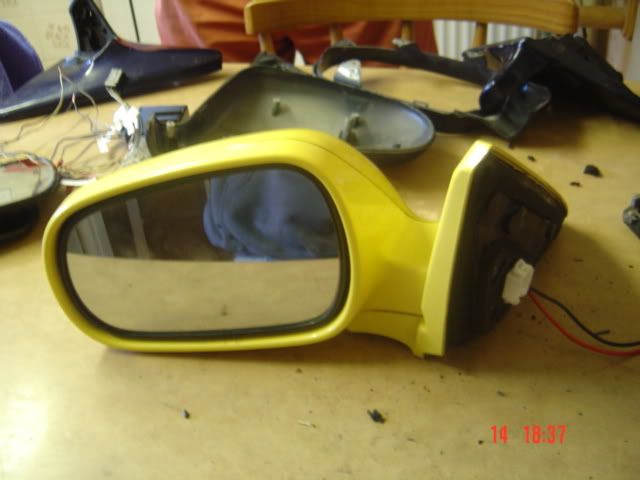
Heres all the parts:
For testing that the mirrors work you will also need a 12v DC power supply, DO NOT USE A CRAP ONE AS IT WILL NOT DELIVER ENOUGH AMPS TO POWER THE FOLDING MOTORS!
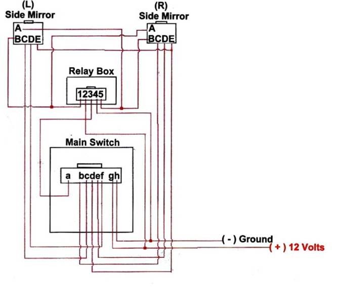
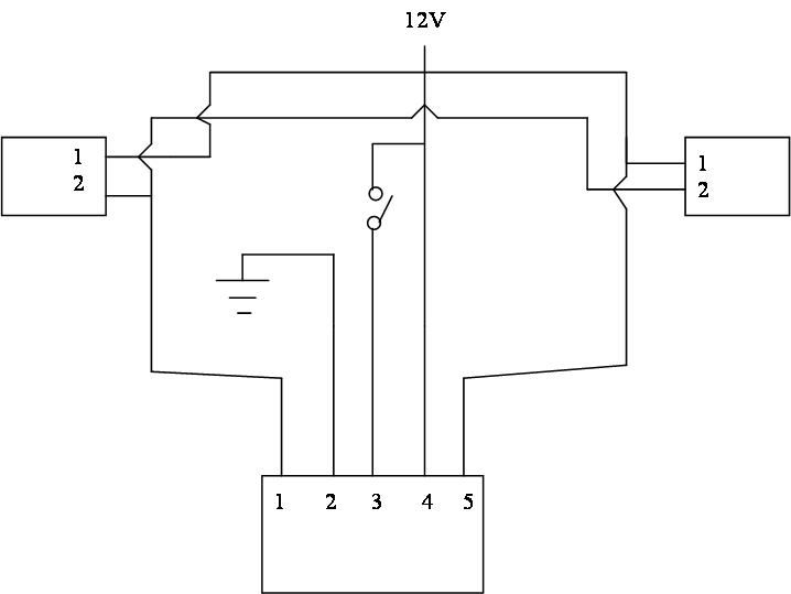
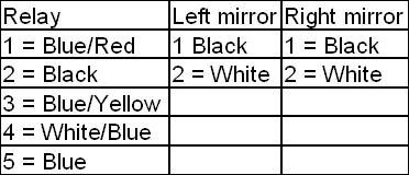
Using this wiring diagram:
And these wire ID's:
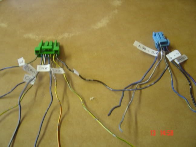
Mark up the main switch and relay harnesses wiht their destinations like this:
DOUBLE CHECK YOUR WIRING!
These wire colours may not be the same as yours, if they arent then its not a big issue, I had several different wire colour ID's all of which partially matched my wire colours and i just followed the diagram and it worked just fine.
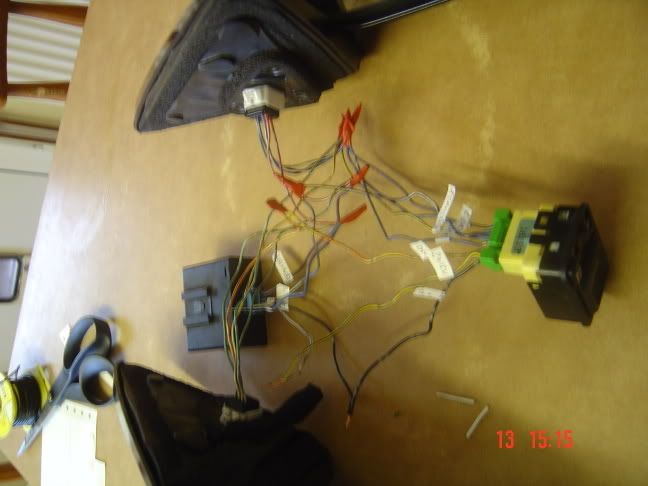
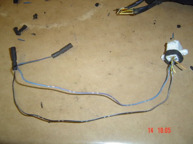
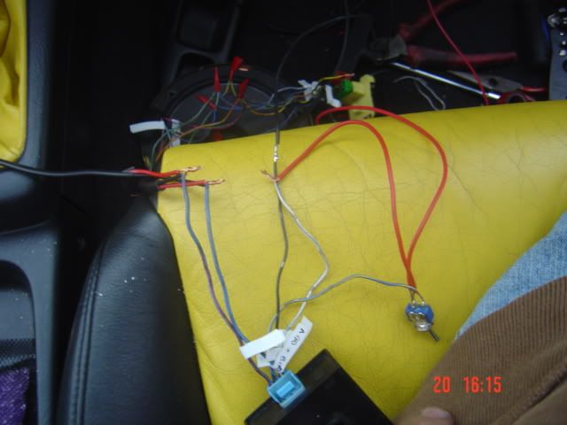
Now connect up all the harnesses, plug them in and they should look like this:
CHECK YOUR WIRING AGAIN
TWICE
Connect up your 12v DC power supply to the wires as shown above.
First test the mirror movement, all directions on both mirrors, then press the the fold button.
At the very least you should hear the relay click, if this happens and the mirrors dont move press the button again to disengage the relay, disconnect the power supply and go find a better one, the one you have is not delivering enough amps.
If nothing happens at all then disconnect immediately , go back and check your wiring, you probably screwed up.
If you have wired it correctly then something is broken. Get hold of me and i will help you to identify what it is that is broken (you will need a multimeter or continuity tester).
Make sure when you test them the mirors arent trying to push themselves up as well as out, they might not have the power to.
This is how i tested mine and mine work.
Its easiest to not try to attempt to use the power folding switch, relay and mirror harnesses, the conversion is waaaaaaaaaaay more complex this way and would involve significant wiring. I am by no means an electronics amateur and although i did figure it out, its not neccesary anyway.
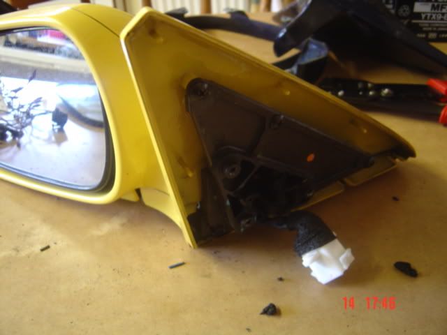
Now that you know the mirror motors and fold relay are operational you need to dissassemble both your original mirrors and your replacement mirrors to fit the power fold motor assemblies into the jordan housings.
When taking them off of the doors, you do not really need to remove the door cards, however for refitting the mirrors and installing the power fold circuit you will. So if you are going to be refitting the mirrors and installing the fold circuit at the same time then you may as well remove the door cards.
There is no real nack to disassembling either of the mirrors, however this order worked for me.
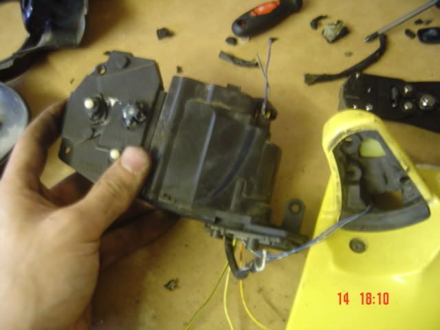
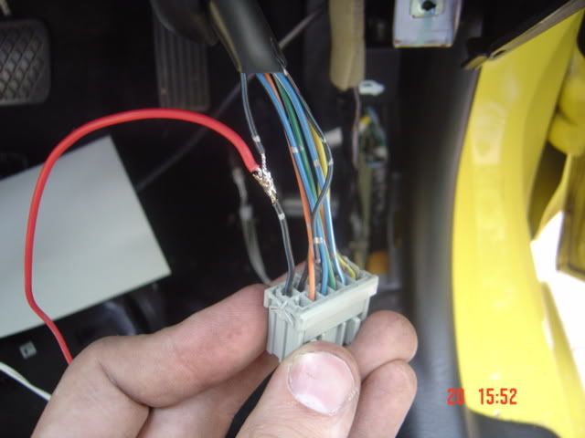
remove the backing rubber and unscrew the white connector.
the stock jordan connector looks like this:
ooo
oo
with the three pins in a row being the power adjust circuit, and the two other ones being the heated mirror circuit.
next pop the mirror off of the linear motors, pressthe mirror around in the shell untill you can see the white actuators, remove the small circlip from the socket on the back of the mirror and pull the mirror off, it takes a bit of force but a flat blade screwdriver helps.
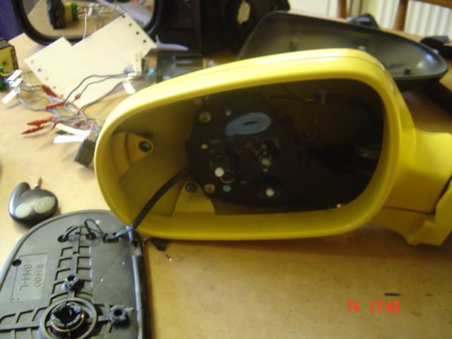
Next unscrew the surround from the case, and pull it off, there are clips around the hinge area which take abit of a pull to get off.
Unscrew the stock adjustment motor assemly, and take out the three screws from underneath the hinge to seperate the body from the backing plate.
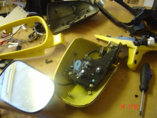
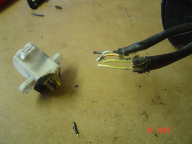
Now cut the power adjust wires at the white connector end leaving enough wire to solder the power folding mirrors adjustment wires onto them
(this picture is of the power fold connector cut off which you have to do as well, make a note of where all the wires went toin case you get confused later).
Take apart the power folding mirrors in the same way.
You should find that the wire colours fro your standard power adjust and the new mirrors power adjust are the same. Pass the heated mirror wires throuogh the same way as the power fold and power adjust wires go in the new mirror folding mechanism.
now solder the wires back up colour to colour and extend the power fold wires (the black and white pair of wires in the new motor assemblies).
thats about it, just make sure all the wires are re-routed corrctly BEFORE soldering them.
Re-assemble the mirrors in the jordan housings, and re-fit to the car.
i havent got around to fitting the power fold section yet but thatll be done next weekend.
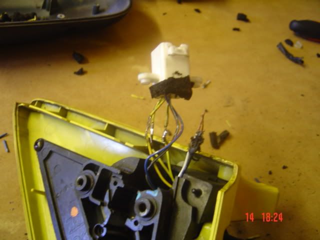
It will operate off of the black and red wires shown here:
Any questions just ask and ill sort you out
Right, now, to fit the wires through from the door to the interior of the car i was planning to pass them through the existing wire harness from the door to car, however this as it turned out was not an option because of the plugs honda use.
So, i had to find another option which is to remove this grommett. Its behind the kick panel in the footwell. This one is on the drivers side and you have to move a coupla things out of the way using a 10mm socket. Its not hard but PM me if you cant see how to do it. The passenger side one is much easier to get at, its behind the standard ECU.
and drill through two skins of panel to pass the wires through like this
Now, extend the wires by LOADS, trust me you will need it.
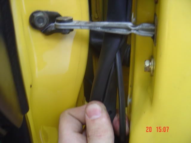
Pass the wires through the door frame as shown here
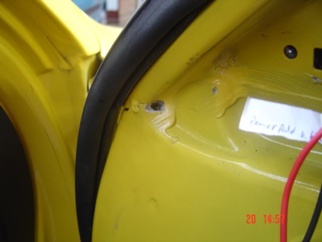
You may need to drill a small hole like this (dont worry you cant see it once the speaker is back on)
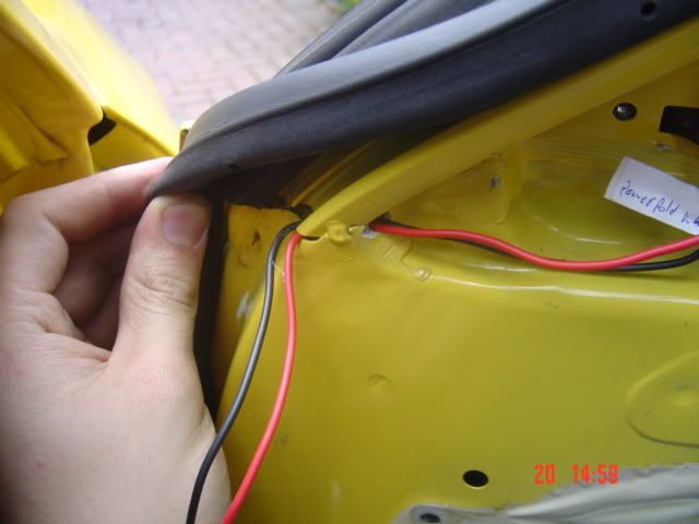
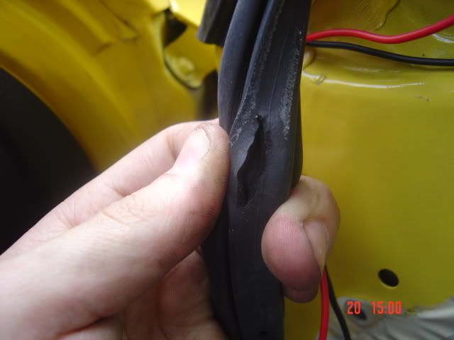
Feed the wires down throught the door seal by cutting two slits, one at the top
and one at the bottom
feed the wires through it and the hole in the door (this is best done the other way round actually, feeding throught the hole then up the seal)
Right, now clip the seal back on and it should look like this
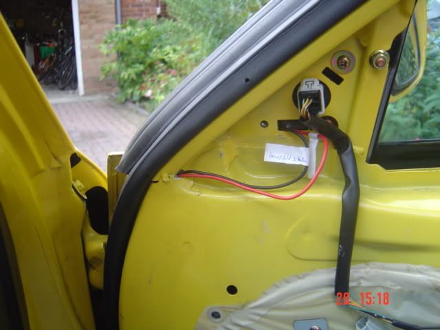
At the other end hook the wires up as shown, (now you realise why you had to remember which ones out of the mirror wires were the white and black ones)
Now all you have to do is hook them up like that and it should all work
The harness will end up like this
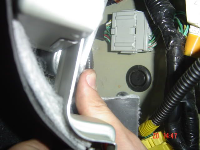
Take the ignition switched 12V supply from the power adjust switch like this
and feed it straight to the whits/blue wire on the harness adn through a "push to make" switch to the blue/yellow switch.
Thats about it. Test the mirrors with everything still apart and then put it all back together again
Go here
http://www.nicktownsend.com/honda/files.php
and check powermirrors.mpg
TIDY!!!!!!!!!!!!!!!!

 ) and I wondered how difficult they are to fit to my ek4?